What is a Digital-to-analog Converter?

Electronic Basics #10: Digital to Analog Converter (DAC)
Catalog |
A digital-to-analog converter, also known as a D/A converter or DAC for short, is a device that converts a digital quantity into an analog quantity. A D/A converter basically consists of four parts, namely a weighted resistor network, an operational amplifier, a reference power supply, and an analog switch. Analog-to-digital converters generally require the use of digital-to-analog converters. An analog-to-digital converter, or A/D converter, or ADC, is a device that converts a continuous analog signal into a discrete digital signal.
Ⅰ Composition and characteristics
The digital-to-analog converter is composed of a digital register, an analog electronic switch, a decoding network, a summing operational amplifier, and a reference voltage source (or constant current source). The current value is then summed by an operational amplifier and converted to a voltage value.

TI digital-to-analog converter DAC8760
Depending on the bit weighted network, different types of DACs can be formed, such as weighted resistor network DAC, R-2R inverted T-resistor network DAC, and single-value current network DAC.
The conversion accuracy of the weighted resistor network DAC depends on the reference voltage VREF, and the accuracy of the analog electronic switch, the operational amplifier, and the value of each weighted resistor. Its disadvantage is that the resistance value of each weighted resistor is different. When the number of bits is large, the resistance value is very different, which makes it very difficult to ensure the accuracy, especially for the production of integrated circuits is very unfavorable, so the circuit is rarely used separately in integrated DACs.
The R-2R inverted T-shaped resistor network DAC consists of several identical R and 2R network sections. Each section corresponds to one input bit. The R-2R inverted T-shaped resistor network DAC is one of the faster working and more used ones. Compared with the weighted resistor network, it has only two resistance values, R and 2R, thus overcoming the disadvantage of having many weighted resistor resistance values and large differences in resistance values.
The current type DAC, on the other hand, switches a constant current source into a resistor network. The constant current source has a great internal resistance, which is equivalent to an open circuit, so together with the electronic switch, it has a relatively small impact on its conversion accuracy. Since most of the electronic switches are non-saturated ECL switching circuits, this DAC can realize high-speed conversion with high conversion accuracy.
Ⅱ Conversion principle
Digital quantities are represented by codes combined by digits. For the entitled code, each code has a certain bit of weight. In order to convert the digital quantity into analog quantity, each 1-bit code must be converted into the corresponding analog quantity according to the size of its bit weight, and then these analog quantities are added together to obtain the total analog quantity proportional to the digital quantity, thus realizing the digital-to-analog conversion. This is the basic principle of forming a digital-to-analog converter.
The figure below represents the correspondence between the 4-bit binary digital quantity and the analog quantity of voltage output after D/A conversion. The figure also shows that the voltage values converted from two adjacent digits are discontinuous, and the voltage difference between the two is determined by the value of the bit weight represented by the lowest code bit. It is the smallest amount of information that can be distinguished, which is what we call expressed by 1 LSB (Least Significant Bit). The maximum voltage output value (absolute value) corresponding to the maximum input digital quantity is expressed by FSR (Full Scale Range).

Figure 1 Correspondence between da converter input digital quantity and output voltage
The D/A converter consists of a digital register, an analog electronic switching circuit, a decoding network, a summation circuit, and a reference voltage. The digital quantity is input and stored in the digital register in serial or parallel mode, and the digital register outputs each digit to control the analog electronic switch of the corresponding bit so that the digit 1 bit generates a current value proportional to its weighted value on the bit weighted network, and then the summation circuit adds up the various weighted values to obtain the analog quantity corresponding to the digital quantity.
Ⅲ Performance indicators
The main characteristics of digital-to-analog converters include the following.
Resolution
The ratio of the minimum output voltage (only the lowest valid bit of the corresponding input digital quantity is "1") to the maximum output voltage (all valid bits of the corresponding input digital quantity are "1"). For example, the N-bit D/A converter has a resolution of 1/(2^N-1). In practice, the resolution size is also expressed in terms of the number of bits of the input digital quantity.
Linearity
The linearity of digital-to-analog conversion is expressed in terms of the magnitude of the nonlinear error. And the percentage of deviation from the ideal input-output characteristic to the ratio of full-scale output is defined as the nonlinear error.
Conversion Accuracy
The conversion accuracy of a D/A converter is related to the structure of the integrated chip of the D/A converter and the configuration of the interface circuit. If other D/A conversion errors are not considered, the conversion accuracy of D/A is the size of the resolution. Therefore, to obtain high accuracy D/A conversion results, it is necessary to ensure that a D/A converter with sufficient resolution is selected first. Also, D/A conversion accuracy is related to the configuration of the external circuit. When the external circuit device or power supply error is large, it will cause a large D/A conversion error, and when these errors exceed a certain level, the D/A conversion produces an error.
In the D/A conversion process, the main factors that affect the conversion accuracy are out-of-tune error, gain error, nonlinear error, and differential nonlinear error.
Conversion speed
The conversion speed is generally determined by the build-up time. From the time the input changes abruptly from full 0 to full 1, until the output voltage stabilizes in the FSR±½LSB range (or the range specified by FSR±x%FSR). This is called the setup time, which is the maximum response time of the DAC, so it is used to measure the speed of conversion.
Ⅳ Conversion method
Parallel digital-to-analog conversion

Figure 2 Structure of a typical parallel digital to analog converter
There are two conversion methods for digital-to-analog conversion: parallel digital-to-analog conversion and serial digital-to-analog conversion. Figure 2 shows the structure of a typical parallel digital-to-analog converter. The digitally operated switches and resistor network in the dashed box are the basic components. The device in the figure generates a weighted current or weight voltage with a fractional value based on the reference quantity through an analog reference voltage and a resistive trapezoidal network. A set of switches controlled by the digital input quantity determines which currents or voltages are summed to form the output quantity. The "weight" is the value represented by each bit of the binary number. For example, for a three-digit binary number "111", the "weight" of the first digit on the right is 20/23=1/8; the second digit is 21/23=1/4; the third digit is 22/23=1/2, and so on for more digits.

Figure 3 The basic circuit of a three-bit digital-to-analog converter
Figure 3 shows the basic circuit of this three-digit digital-to-analog converter. The reference voltage VREF generates a binary weight current in R1, R2, and R3, and the current passes through the switch. When the value of the bit is "0", it is connected to the ground; when the value of the bit is "1", it is connected to the output summation bus. The sum of several currents is passed through the feedback resistor Rf to produce the output voltage. The voltage polarity is opposite to the reference quantity. Each change of 1 in the input digital quantity causes only 1/23=1/8 change in the output relative quantity, which is called the resolution of the digital-to-analog converter. The higher the number of bits, the higher the resolution and the higher the accuracy of the conversion. Most of the digital-to-analog converters used in industrial automatic control systems are 10-bit, 12-bit, with a conversion accuracy of 0.5 to 0.1%.
Serial digital-to-analog conversion
Serial digital-to-analog conversion is to convert the digital quantity into the number of pulse sequences, one pulse is equivalent to one unit of digital quantity, then each pulse is changed into unit analog quantity. All the unit analog quantities are added together to get the analog output proportional to the digital quantity, so as to realize the conversion of digital quantity and analog quantity.
With the rapid development and popularity of digital technology, to improve the performance index of the system, digital computer technology is widely used for the processing of signals. As the actual objects of the system are often some analog quantities (such as temperature, pressure, displacement, image, etc.), to make the computer or digital instrument can recognize and process these signals, these analog signals must first be converted into digital signals. And the digital quantity outputted by the computer after analysis and processing often needs to be converted to the corresponding analog signal in order to be accepted by the actuator. This requires a circuit that acts as a bridge between analog and digital signals - an analog-to-digital and digital-to-analog converter.
The circuit that converts an analog signal into a digital signal is called an analog-to-digital converter (referred to as an A/D converter or ADC). A/D converters and D/A converters have become indispensable interface circuits in computer systems.
To ensure the accuracy of system processing results, A/D converters and D/A converters must have sufficient conversion accuracy; to achieve real-time control and detection of rapidly changing signals, A/D and D/A converters also require a high conversion speed. Conversion accuracy and conversion speed are the important technical indicators of A/D and D/A converters. With the development of integration technology, many monolithic and hybrid integrated A/D and D/A converters have been developed and produced, which have more and more advanced technical specifications.
1.What is digital to analog converter examples?
An example of a DAC device is a modem. A modem requires DAC to convert data to analog signals, which can be carried by a telephone wire. Another example of a DAC device is a video adapter.
2.Which digital to analog converter is best?
PROZOR 192KHz Digital to Analog Audio Converter.

Techole Digital to Analog Audio Converter.

RooFull Digital Audio Converter Adapter.

RooFull Digital-to-Analog Audio Converter.
3.Why do we use DAC?
DACs are commonly used in music players to convert digital data streams into analog audio signals. They are also used in televisions and mobile phones to convert digital video data into analog video signals. These two applications use DACs at opposite ends of the frequency/resolution trade-off.
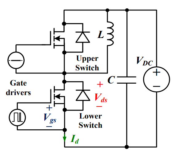 Discovering New and Advanced Methodology for Determining the Dynamic Characterization of Wide Bandgap DevicesSaumitra Jagdale15 March 20242346
For a long era, silicon has stood out as the primary material for fabricating electronic devices due to its affordability, moderate efficiency, and performance capabilities. Despite its widespread use, silicon faces several limitations that render it unsuitable for applications involving high power and elevated temperatures. As technological advancements continue and the industry demands enhanced efficiency from devices, these limitations become increasingly vivid. In the quest for electronic devices that are more potent, efficient, and compact, wide bandgap materials are emerging as a dominant player. Their superiority over silicon in crucial aspects such as efficiency, higher junction temperatures, power density, thinner drift regions, and faster switching speeds positions them as the preferred materials for the future of power electronics.
Read More A Comprehensive Guide to FPGA Development BoardsUTMEL11 September 20257956
This comprehensive guide will take you on a journey through the fascinating world of FPGA development boards. We’ll explore what they are, how they differ from microcontrollers, and most importantly, how to choose the perfect board for your needs. Whether you’re a seasoned engineer or a curious hobbyist, prepare to unlock new possibilities in hardware design and accelerate your projects. We’ll cover everything from budget-friendly options to specialized boards for image processing, delve into popular learning paths, and even provide insights into essential software like Vivado. By the end of this article, you’ll have a clear roadmap to navigate the FPGA landscape and make informed decisions for your next groundbreaking endeavor.
Read More Applications of FPGAs in Artificial Intelligence: A Comprehensive GuideUTMEL29 August 20252196
This comprehensive guide explores FPGAs as powerful AI accelerators that offer distinct advantages over traditional GPUs and CPUs. FPGAs provide reconfigurable hardware that can be customized for specific AI workloads, delivering superior energy efficiency, ultra-low latency, and deterministic performance—particularly valuable for edge AI applications. While GPUs excel at parallel processing for training, FPGAs shine in inference tasks through their adaptability and power optimization. The document covers practical implementation challenges, including development complexity and resource constraints, while highlighting solutions like High-Level Synthesis tools and vendor-specific AI development suites from Intel and AMD/Xilinx. Real-world applications span telecommunications, healthcare, autonomous vehicles, and financial services, demonstrating FPGAs' versatility in mission-critical systems requiring real-time processing and minimal power consumption.
Read More 800G Optical Transceivers: The Guide for AI Data CentersUTMEL24 December 20251026
The complete guide to 800G Optical Transceiver standards (QSFP-DD vs. OSFP). Overcome supply shortages and scale your AI data center with Utmel Electronic.
Read More Xilinx FPGAs: From Getting Started to Advanced Application DevelopmentUTMEL09 September 20252883
This guide is your comprehensive roadmap to understanding and mastering the world of Xilinx FPGA technology. From selecting your first board to deploying advanced AI applications, we'll cover everything you need to know to unlock the potential of these remarkable devices. The global FPGA market is on a significant growth trajectory, expected to expand from USD 8.37 billion in 2025 to USD 17.53 billion by 2035. This surge is fueled by the relentless demand for high-performance, adaptable computing in everything from 5G networks and data centers to autonomous vehicles and the Internet of Things (IoT). This guide will walk you through the key concepts, tools, and products in the Xilinx ecosystem, ensuring you're well-equipped to be a part of this technological revolution.
Read More
Subscribe to Utmel !
![AT88SC25616C-PU]() AT88SC25616C-PU
AT88SC25616C-PUMicrochip Technology
![FM3164-G]() FM3164-G
FM3164-GCypress Semiconductor Corp
![HCS301-I/P]() HCS301-I/P
HCS301-I/PMicrochip Technology
![L9660TR]() L9660TR
L9660TRSTMicroelectronics
![MOC3062VM]() MOC3062VM
MOC3062VMON Semiconductor
![MOC3020SR2M]() MOC3020SR2M
MOC3020SR2MON Semiconductor
![FGBS3040E1-F085]() FGBS3040E1-F085
FGBS3040E1-F085ON Semiconductor
![ATSHA204-TSU-T]() ATSHA204-TSU-T
ATSHA204-TSU-TMicrochip Technology
![AD8196ACPZ]() AD8196ACPZ
AD8196ACPZAnalog Devices Inc.
![TLE8110EDXUMA1]() TLE8110EDXUMA1
TLE8110EDXUMA1Infineon Technologies


